
Phase 1
Requirements and concept
Define interfaces, motion, loads, dimensions, materials and an initial parametric concept.
Projects · Mechanical Engineering and CAD
Parametric 3D CAD for mechanical parts and assemblies, from concept geometry to manufacturing drawings and iterative prototype development.
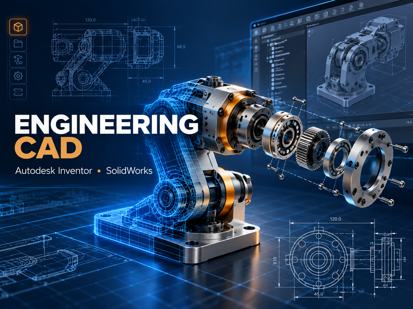
Engineering CAD converts functional requirements into controlled 3D parts, assemblies and drawings that can be reviewed, manufactured and revised.
The workflow can cover robotic mechanisms, linkages, housings, brackets, fixtures and other engineered components using Autodesk Inventor and SolidWorks.
Design reviews consider fit, motion, tolerances, interfaces, materials, fasteners, serviceability and manufacturability before physical prototyping.
Roadmap
Phase 1
Define interfaces, motion, loads, dimensions, materials and an initial parametric concept.
Phase 2
Develop parts and assemblies, run fit and interference checks, and prepare manufacturing documentation.
Phase 3
Fabricate or print selected parts, test the mechanism, capture issues and feed measured results back into the CAD model.